SOLVENT RECOVERY AND WASTE GAS PURIFICATION
PROCESS DESCRIPTION
During production of chemicals or pharmaceutical agents, solvent-containing exhaust gases often escape from the reaction vessels. The displacement air from petrochemical tank farms often contains gasoline fumes, and HCFCs (Hydrochlorofluorocarbons) are released in the recycling of refrigerators.
In the exhaust gas streams can be found Dichloromethane (methylene chloride), chlorobenzene, diethyl ether, chloroform, acetone, silicon compounds (siloxanes), alcohols, pentane and gasoline vapors, HFCs, CFCs and others. Gaseous substances such as Methyl chloride (chloromethane) or CFC R 12 can also be recovered.
If these exhaust gas streams are passed through cooled heat exchangers, the vaporous substances liquefy in them. These can then be easily separated from the gas stream and returned to the tank or reused in production.
GAS APPLICATIONS
If the heat exchangers are cooled with liquid nitrogen, the process is referred to as “cryocondensation”. Because of the extremely low cooling temperatures (-196 ° C), very high recovery rates are achieved, and efficient cleaning of the exhaust gas streams.
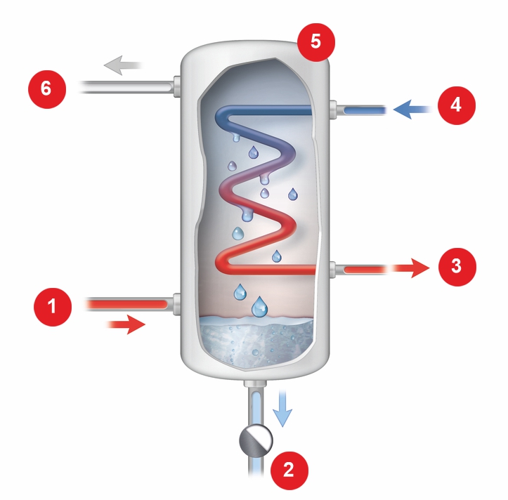
- Raw gas | 2. Condensate | 3. Nitrogen (gaseous) | 4. Nitrogen (liquid) | 5. Cryo condensator | 6. Clean gas
Advantages:
- Exhaust air purification with simultaneous recovery of the solvents
- Cost savings through recycling of the solvents
- Compliance with the emission limit values (TA-Luft)
- Double use of nitrogen: The nitrogen used for cooling can be used as a gas for inerting.
- Pilot plants for customer trials
- Individual plant design
- Experience from over 80 installations worldwide
ELME MESSER GAAS SOLUTIONS
In practice, cryo condensation is a complex process because at low cooling temperatures, the vapors in the condensers freeze and then clog the apparatus. In addition, ice fogs are formed which lead to higher residual loadings in the exhaust gas flow than would be expected due to the low process temperatures.
This can be avoided by using cold gaseous nitrogen instead of liquid nitrogen as a coolant, as in the DuoCondex process developed by Messer. The cryo condensator is divided into two parallel tube bundles. The cold gas is generated in an upstream evaporator (thermo controller). Into this thermo controller liquid nitrogen is injected from a storage tank. The liquid nitrogen evaporates and then enters as a cold gas in the first tube bundle of the cryo condensator. Here it transfers its cold to the exhaust gas flowing from below and warms up. The now warm nitrogen is now fed back to the evaporator and serves as a heat source for the evaporation of nitrogen. It cools down again and is used again as cold gas, this time for cooling the second tube bundle. From every kg of liquid nitrogen without energy losses, 2 kg of cold gaseous nitrogen are generated for the cooling of the cryo condensator.
To the same extent as the cold gas warms, the gas stream to be cleaned cools down and the residual load drops below the limit values required by environmental legislation. Downstream cleaning stages are not required. The harmful vapors liquefy and dissipate, and the heated nitrogen flows under pressure into the customer’s plant network for further use as an inert gas.

- Raw gas
- Condensat
- Nitrogen (gaseous)
- Nitrogen pipeline
- Thermo controler
- Nitrogen (gaseous)
- Clean gas
- Cryo condensator
DuoCondex systems are individually designed according to customer requirements and optimally designed for each individual case. For this purpose, the experience of more than 80 cryo-condensation plants installed by Messer worldwide is available.
Upon request, we will also be happy to demonstrate the process on-site with our mobile pilot plant. Under real operating conditions, the data required for a configuration can be determined most reliably.